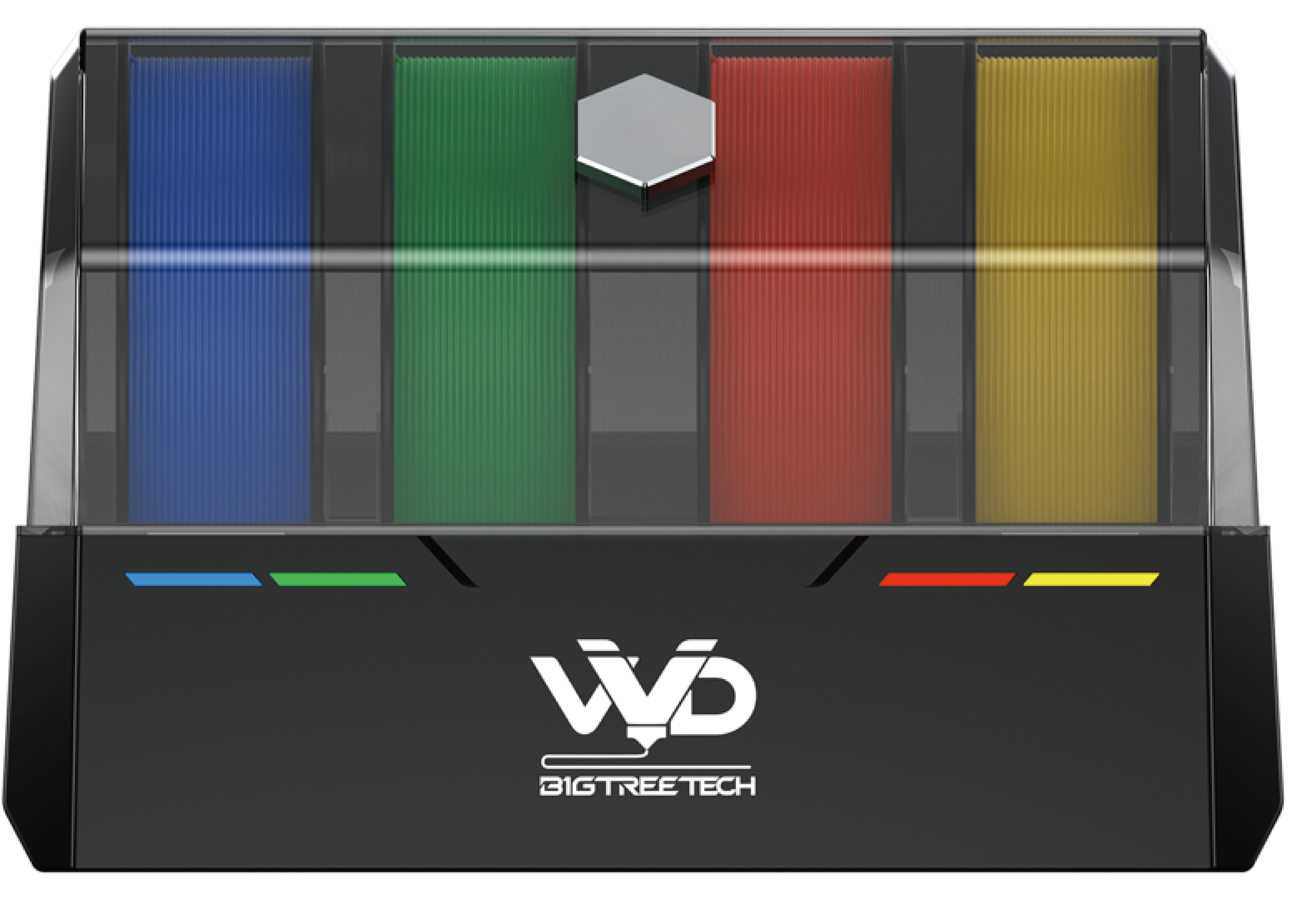
BIGTREETECH ViViD
Product Link: Buy Here
Preface
Thank you for choosing the BIGTREETECH ViViD Multi-Color Management System. This manual provides step-by-step guidance for hardware installation, firmware configuration, and slicer setup.
It is designed for users already familiar with basic Klipper operation and configuration.
Please note: This documentation applies specifically to ViViD hardware used with the MMS (Multi-Material System) software. If you choose to use HappyHare, please refer to its official documentation for configuration instructions.
Assembly Guide
PTFE Tube Connection
Connecting the Buffer to the ViViD
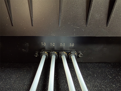
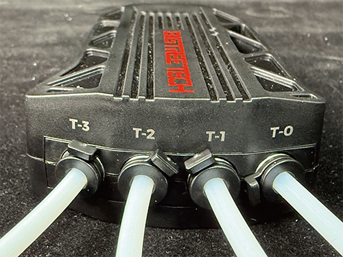
To install the unit, first release the clips and connect the Buffer to the ViViD using the PTFE tubing, ensuring each port is matched correctly: T-0 to T-0, T-1 to T-1, T-2 to T-2, and T-3 to T-3. Once connected, secure the clips to lock the tubes in place.
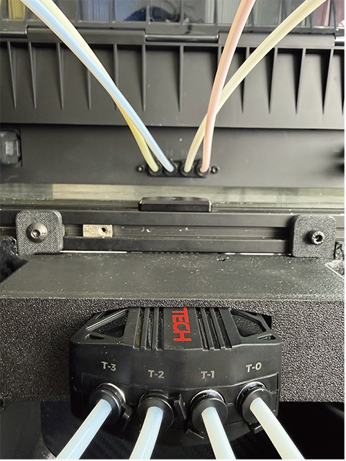
For VORON printer users, a modified exhaust filter housing is available to simplify tube routing; this housing features a dedicated slot for the Buffer and allows the ViViD to be mounted on top of the printer's enclosure.
Please download the print files here.
Important: PTFE Tube Routing Requirements
When routing the PTFE tubes between the ViViD and the Buffer, ensure that the tube path is smooth and free of sharp bends.
The minimum bending radius must not be less than 60 mm; a radius of 100 mm or greater is strongly recommended. Excessively tight bends will significantly increase friction, which can severely reduce filament switching success rates and may cause filament breakage.
Connecting the Buffer to the Toolhead
After completing the tube connections, ensure the locking clip at the Buffer outlet is securely installed. Without this clip, repeated filament tension may cause the PTFE tube to detach.
Power Connection
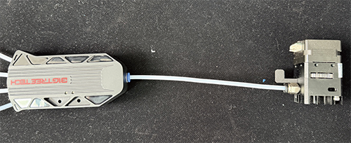
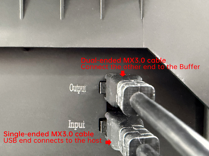
Two wiring methods are provided, which are functionally identical. Please choose based on your setup preference.
-
Method 1:
Connect a USB cable between the host USB and the ViViD Input port.
Connect a dual-head MX3.0 cable between the ViViD Output and the Buffer Input.
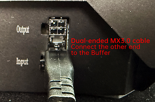
-
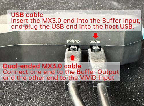
Method 2:
Connect a USB cable between the host USB and the Buffer Input port.
Connect a dual-head MX3.0 cable between the Buffer Output and the ViViD Input.
Power Supply Instructions:
-
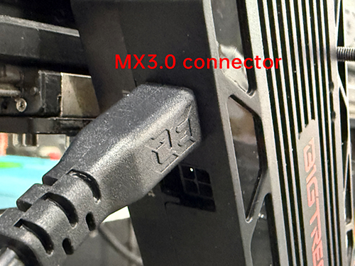
The ViViD operates on AC power. Please use a standard three-prong power cable (IEC C13) to connect the ViViD to an AC power outlet.
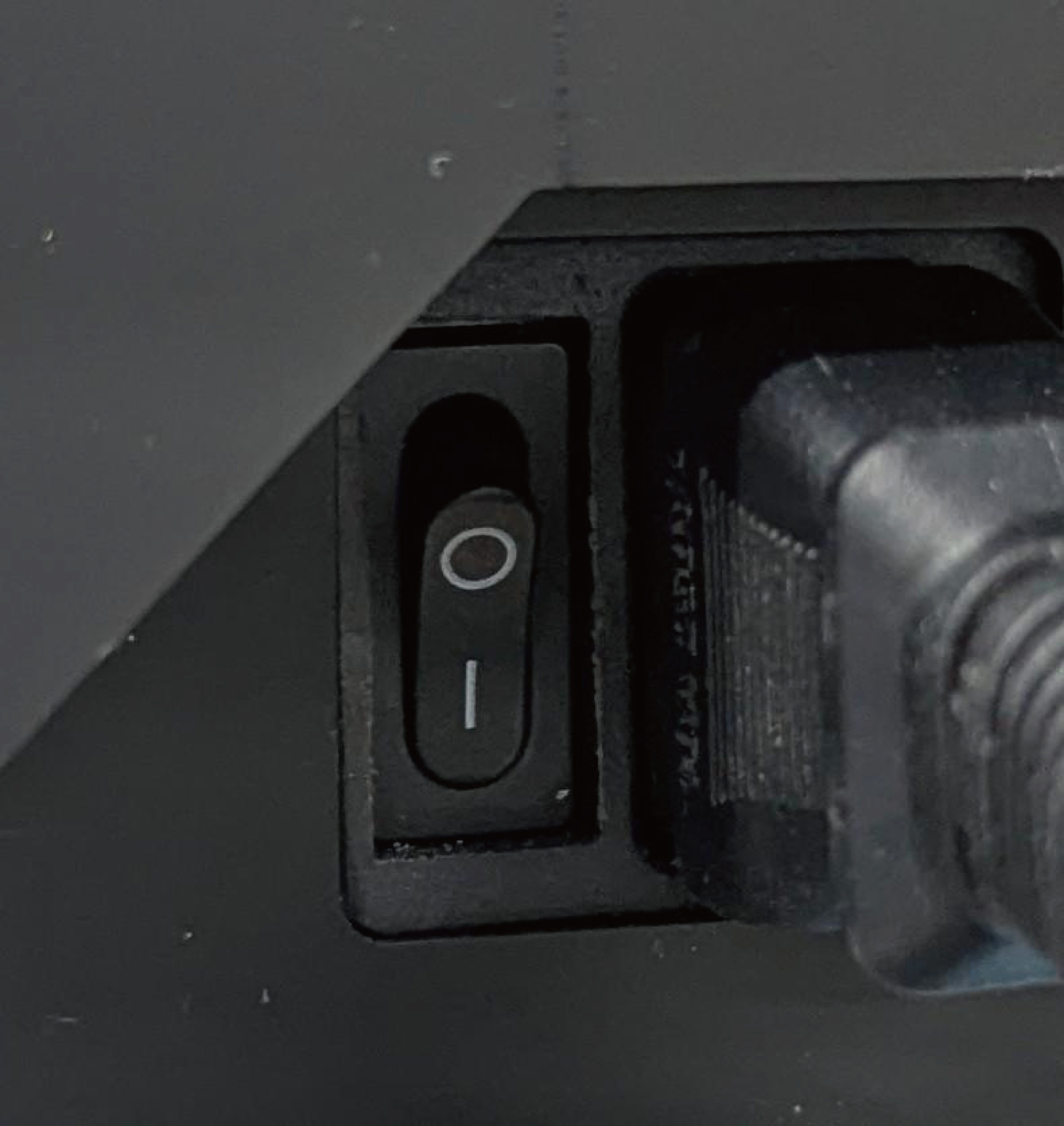
-
After connecting the power cable, switch the power switch to the ON position (press the "|" symbol down).
-
Once powered on, a light red indicator light signifies that the software configuration is incomplete or that a successful connection to Klipper has not yet been established.
Optional USB Signal Improvement
Installing USB Hub and Ferrite Cores
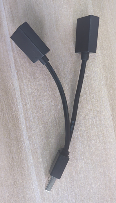
Some controller boards have USB interfaces driven directly by the SOC (e.g., BTT Pi V1.2 series, BTT Pi2 series), which results in weaker USB signals and unstable long-distance communication. For optimal performance when connecting ViViD to such boards, it is recommended to use the included USB hub. The hub will enhance USB signal strength, support greater transmission distances, and improve overall signal stability.
Ferrite cores can help prevent USB signal interference.
If the USB cable is routed near stepper motors, their operation may disrupt USB communication. In this case, it is recommended to install ferrite cores on the motor cables, placing them as close as possible to the controller board connections.
Software Configuration
MMS Software Deployment
Installation Steps
-
Enter the user directory:
-
Clone the repository:
-
Enter the directory and run the install.sh:
Script Configuration Guide
After running install.sh, the script will guide you through the setup: Enter “y” to confirm/enable, “n” to decline
Installation Steps (top to bottom):
-
Version Check:
-
Device Serial Port Check:
If serial ports are detected: The script prompts you to confirm whether one of the listed ports is the correct serial port for the device.
If not detected, you will be asked whether to continue installation.

-
Module Configuration:
Confirm whether the “Cutter” is enabled
Confirm whether the “Entry Sensor” is enabled
Confirm whether “Purge” and “Brush” are enabled
-
Restart Klipper:
After the script completes, it will request a Klipper restart to apply changes. This step may require password entry.
-
ViViD KlipperScreen Integration (Optional):
If KlipperScreen is already installed, you may press “Y” to install the ViViD-modified KlipperScreen version, which includes ViViD filament management menus.
A restart prompt will appear once installation is complete.
Version Upgrade
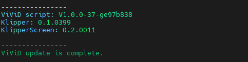
To upgrade the MMS in the future, run the following commands to update the system. Once the update is complete, the message ViViD update is complete will be displayed.
MMS Software Configuration
ID Configuration (Serial ID)
Configuration file location: config/bigtreetech-mms/mms/mms.cfg
If startup fails or you see errors such as “unable to connect MCU ‘vivid’” or “unable to connect MCU ‘buffer’,” please check whether the serial IDs are configured correctly.
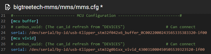
Note: If the serial ID was detected during installation, it will be automatically filled in, and no manual changes are required.
Entry Sensor Configuration
Configuration file location: config/bigtreetech-mms/mms/mms.cfg
If your toolhead has an “Entry Sensor” installed approximately 5–15 mm before the extruder gears, uncomment the configuration and set the correct entry_sensor pin.
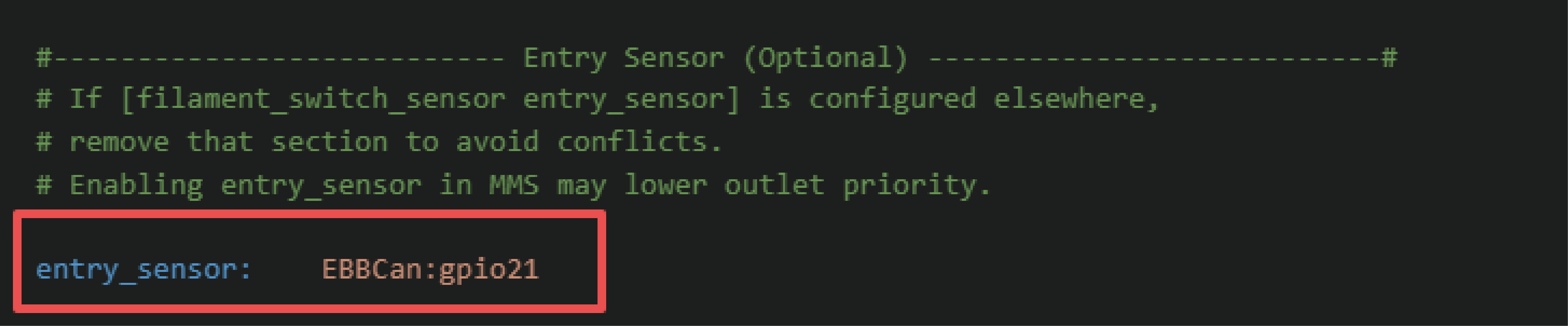
Important: This sensor is critical for accurate filament switching. Without it, the MMS software must estimate filament position using the Buffer sensor alone, which may reduce system reliability and consistency.
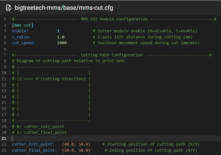
Cutter Configuration
Configuration file location: config/bigtreetech-mms/base/mms-cut.cfg
This file defines the cutter action installed on the toolhead.
-
Motion Logic: Move from
initposition tofinalposition, perform the cut, then return toinit. -
Coordinates: X axis, Y axis.
-
Compatibility: Supports Filametrix (X-axis) and A4T (Y-axis).
-
Setup Method: After homing, manually move the toolhead in KlipperScreen or web UI like Mainsail to determine the cutter's initial impact coordinates (
cutter_init_point) and final installed coordinates (cutter_final_point).
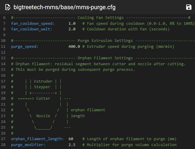
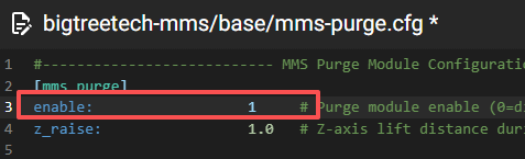
Purge Configuration
Configuration file location: config/bigtreetech-mms/base/mms-purge.cfg
MMS uses Purge configuration to purge residual filament after loading.
| Variable | Description |
|---|---|
| enable | Enable/disable purge (1/0) |
| orphan_filament_length | Purge length |
| purge_modifier | Length multiplier |
| tray_point | Defines the purge and docking position. |
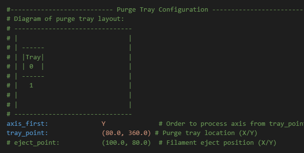
Configuration Note: After the printer completes the Home operation, you can manually move the toolhead using KlipperScreen, Mainsail, or other web-based interfaces to identify and confirm the toolhead position used for purging (tray_point).
The eject_point parameter is intended for purge systems equipped with a filament ejection mechanism. When this feature is enabled, the purge sequence operates as follows: the toolhead first performs the purge at the tray_point, then moves to the eject_point to eject the purged filament.
Note: To prevent filament overflow or oozing from affecting the printed model during filament feeding and purging, configure the tray_point and eject_point at positions outside the normal printing area.
Even when the purge function is disabled, the tray_point is still used as the docking position during filament swaps (Swap). Therefore, it must be correctly configured to match the specific machine setup.
Brush Configuration
Configuration file location: config/bigtreetech-mms/base/mms-purge.cfg
Defines nozzle wiping movement in the XY directions.
-
Tapping is usually executed after wiping completes.
-
Configuration Instructions:
After homing, manually move the toolhead in KlipperScreen or web UI like Mainsail to determine the wipe coordinates (wipe-point).
Variable Description enable Enable/disable this feature (1/0) wipe-point Set wipe position coordinates wipe_times Set number of wipes 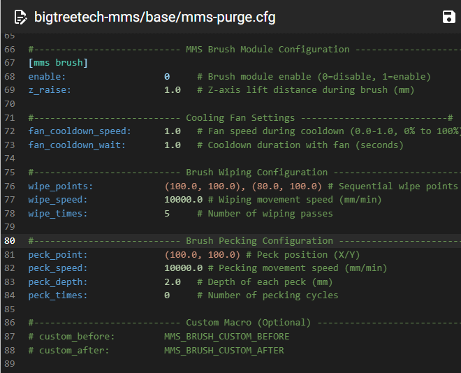
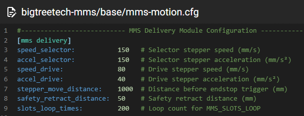
Motion Parameter Configuration
Configuration file: config/bigtreetech-mms/base/mms-motion.cfg
If the filament moves smoothly during testing but you observe that the Drive Gear is severely grinding or chewing into the filament, this usually indicates that the extrusion force is too high or that the drive acceleration is set excessively. Please adjust the "mms-delivery.cfg file": reduce speed_drive and reduce accel_drive.
Bowden Length Calibration Before Printing
Command: MMS_BOWDEN_CALIBRATION
After all four filaments have entered ViViD, enter MMS_BOWDEN_CALIBRATION in the Console. The filament in each slot will calibrate the Bowden tube length in sequence.
The calibrated length is saved in real time. If an abnormality occurs during calibration and results in incorrect parameters, please run the calibration again.
Info
After completing the above file configurations, ViViD is ready for operation. For further installation or debugging, please refer to Section 6: Tuning Guide in this manual. For more parameter descriptions, please view the documentation.
ViViD Operation Logic and Debug Commands
It is strongly recommended to install the Entry Sensor before using ViViD.
The following is the overall movement logic after installing the entry sensor.
ViViD Workflow
For ease of understanding, the ViViD filament path can be simplified as: Buffer (T0-T3) -> Gate Sensor -> Entry Sensor -> Extruder -> Nozzle.
A standard MMS Swap (filament change) process is as follows:
Step 1: Eject Check (Unload Decision)
-
Condition check:
If either the Entry Sensor or the Gate Sensor is triggered, this indicates that filament is already loaded, and the system will enter the Eject (Unload) process.
-
Otherwise:
If neither sensor is triggered, the system assumes no filament is currently loaded and will skip the eject process, proceeding directly to the “Load Process (Step 3)”.
Step 2: Eject Process (Unloading Filament)
-
Filament Ramming and cutting:
If the Entry Sensor is triggered and the hotend temperature is above the extrusion temperature, the extruder will first perform a filament ramming action to shape the filament end. It will then execute the CUT action, and afterwards attempt to unload 120 mm of filament.
-
High-speed unloading:
Once the Entry Sensor is released, the system performs a long, high-speed retraction. Retraction continues until the Gate Sensor is released.
-
Eject completion:
After the main retraction, a short additional retraction is performed. Once completed, the eject process ends.
Step 3: Load Process (Loading Filament)
-
Selector adjustment:
After the Eject Process is completed, MMS proceeds with loading the new filament. The system first adjusts the Selector. The selector rotates until the correct position is reached and the corresponding selector sensor is triggered.
-
High-speed loading:
The system then performs a long-distance, high-speed filament feed. Loading continues until the Entry Sensor is triggered (if installed), or the Outlet Sensor is triggered (if no entry sensor is installed).
-
Transition to Charge:
Then proceed to the Charge process. The goal of the Load Process is to position the filament tip precisely at the entry point of the extruder drive gears, ready to be gripped.
Step 4: Charge Process
The Charge process ensures the extruder securely grips the filament and confirms whether the grip has been successfully established.
-
Grip attempt: The extruder will attempt to grip the filament. A successful grip is indicated by a slight, corresponding movement of the Drive Wheel.
-
State detection: During this stage, MMS continuously monitors the buffer runout sensor and the outlet sensor to determine whether the filament has been correctly gripped by the extruder.
-
Failure handling: If the filament is not successfully gripped, the system will initiate an Eject sequence and then retry the Load process. The default number of retries is 3, which can be adjusted in the configuration file.
-
Success handling: If the filament is successfully gripped, the system proceeds to the Purge Process.
Step 5: Purge Process
-
Movement and initial purge: If the enable parameter is set to 1, the toolhead moves to specified coordinates then performs a short, low-speed filament purge.
-
Purging: After the initial extrusion, a higher-speed purge is executed. (The purge length and speed are fully configurable in the configuration file.)
-
Transition to Brush: Once purging is complete, the system enters the Brush Process.
Step 6: Brush Process
-
Nozzle cleaning: If the enable parameter is set to 1, the toolhead moves to the specified Brush coordinates and moves back and forth a specified number of times to clean nozzle residue.
-
Process completion: After the Brush Process finishes, the current swap cycle ends. This marks the successful completion of a full filament swap.
Console Commands
The filament slots corresponding to ViViD's T0 through T3 are defined as SLOT0-SLOT3.
| Command (Alias) | Purpose | Example (using SLOT0) |
|---|---|---|
| MMS | Show current MMS version | MMS |
| MMS STATUS | Show current status of all sensors | MMS STATUS |
| MMS_POP | Retract filament ends to a standby position in front of the Gate sensor | MMS_POP SLOT=0 |
| MMS_SELECT | Control selector to select specified SLOT | MMS_SELECT SLOT=0 |
| MMS_LOAD | Execute load action for specified SLOT (includes SELECT) | MMS_LOAD SLOT=0 |
| MMS_MOVE | Control filament movement in specified slot toward extruder by specified length (negative for reverse) | MMS_MOVE SLOT=0 DISTANCE=10 |
| MMS_EJECT | Unload the currently loaded filament | MMS_EJECT |
| MMS_BUFFER_ACTIVATE | Enable asynchronous loading function | MMS_BUFFER_ACTIVATE |
| MMS_BUFFER_DEACTIVATE | Disable asynchronous loading function | MMS_BUFFER_DEACTIVATE |
| MMS_CUT | Execute MMS built-in cutter action (can be used to verify cutter coordinates) | MMS_CUT |
| MMS_PURGE | Perform purging according to configured purge parameters (can be used independently for parameter and position verification) | MMS_PURGE |
| T* | Load filament from the corresponding slot into the extruder | T0 / T1 / T2 / T3 |
About T commands: The T commands internally include the following processes:
LOAD,CHARGE, andPURGE. If filament from another slot is already loaded when a T command is issued, the system will first performCUT,EJECT, andSELECT. It will then continue withLOAD→CHARGE→PURGE. T commands are commonly used in slicers to execute a complete filament change process.
Fault Detection
When an abnormal condition occurs, users can send the “MMS_STATUS” command to analyze the current system state.
Note: If the Entry Sensor is not configured, Entry Sensor status will not be displayed.
-
Slot [0]→ T0 (leftmost slot) -
Slot [1]→ T1 (second from the left) -
Slot [2]→ T2 (third from the left) -
Slot [3]→ T3 (rightmost slot) -
[selector] indicates whether the corresponding slot is selected.
-
1 → The corresponding slot is selected
-
0 → The corresponding slot is not selected
-
-
[inlet] Indicates whether the filament inlet switch is triggered.
-
0 → Filament has not entered ViViD; inlet switch not triggered
-
1 → Filament has entered ViViD; inlet switch triggered
-
-
[gate] Indicates whether the Buffer inlet (Gate) sensor is triggered.
-
0 → Not triggered; filament has not entered the Buffer
-
1 → Triggered; filament has entered the Buffer
-
-
[outlet] Indicates whether the Buffer outlet sensor is triggered.
When filament enters nozzle and begins extrusion, used as judgment criterion for whether it has reached Extruder.
-
0 → Not triggered; filament is not being extruded
-
1 → Triggered; filament is under extrusion pressure
If the console reports three consecutive failures to trigger the outlet sensor, this indicates a filament feeding abnormality.
In this case, users should inspect the filament path and check whether the feeding channel is unobstructed.
-
Feature Overview
Filament Loading
MMS supports automatic filament loading, however this mode is not recommended for beginners. To make operation easier to understand and control, we recommend using the provided semi-automatic loading method.
Loading Filament to the Buffer
-
Using KlipperScreen (ViViD-adapted version):
-
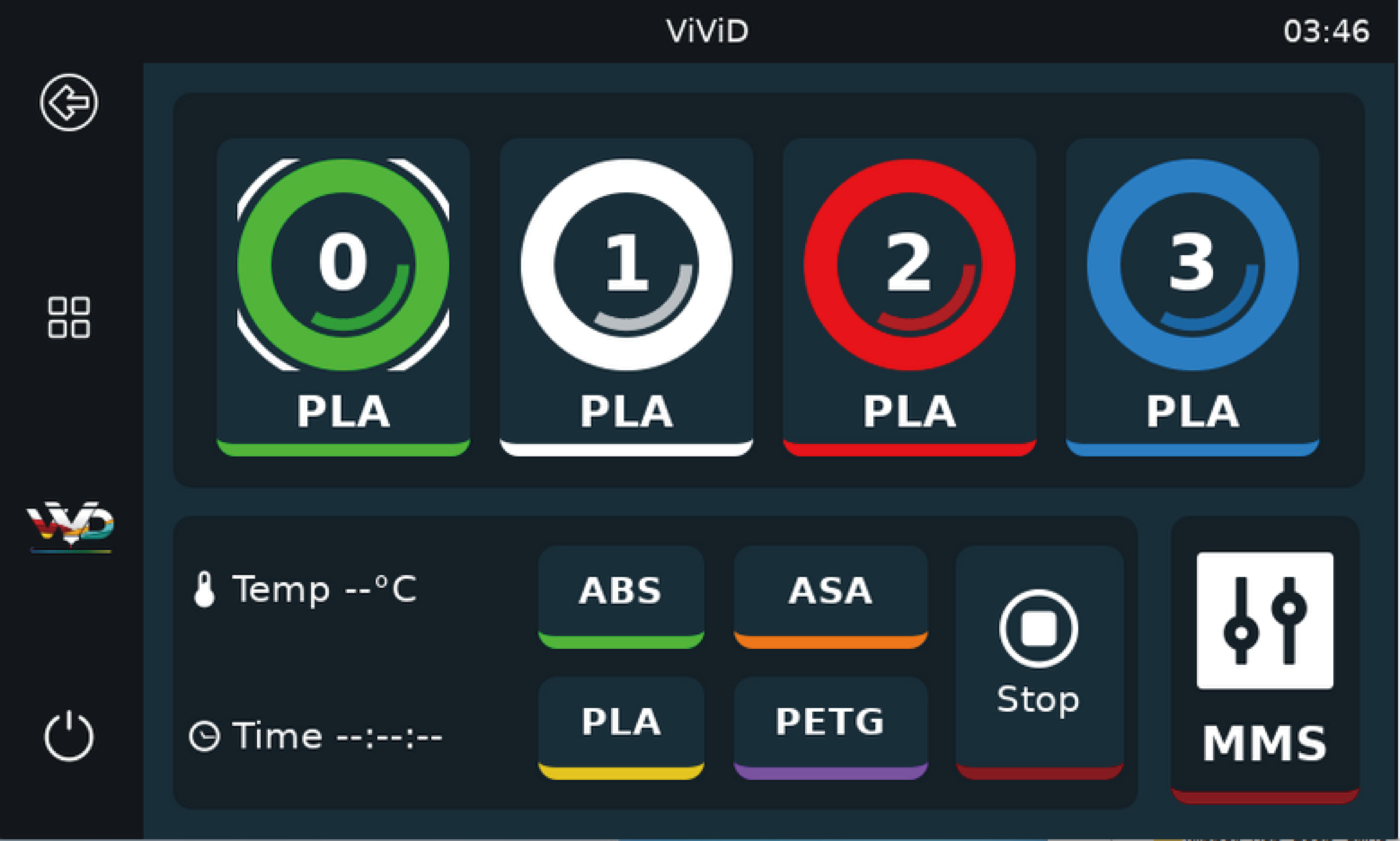
On KlipperScreen, tap the corresponding slot to enter the filament management interface for that slot.
-
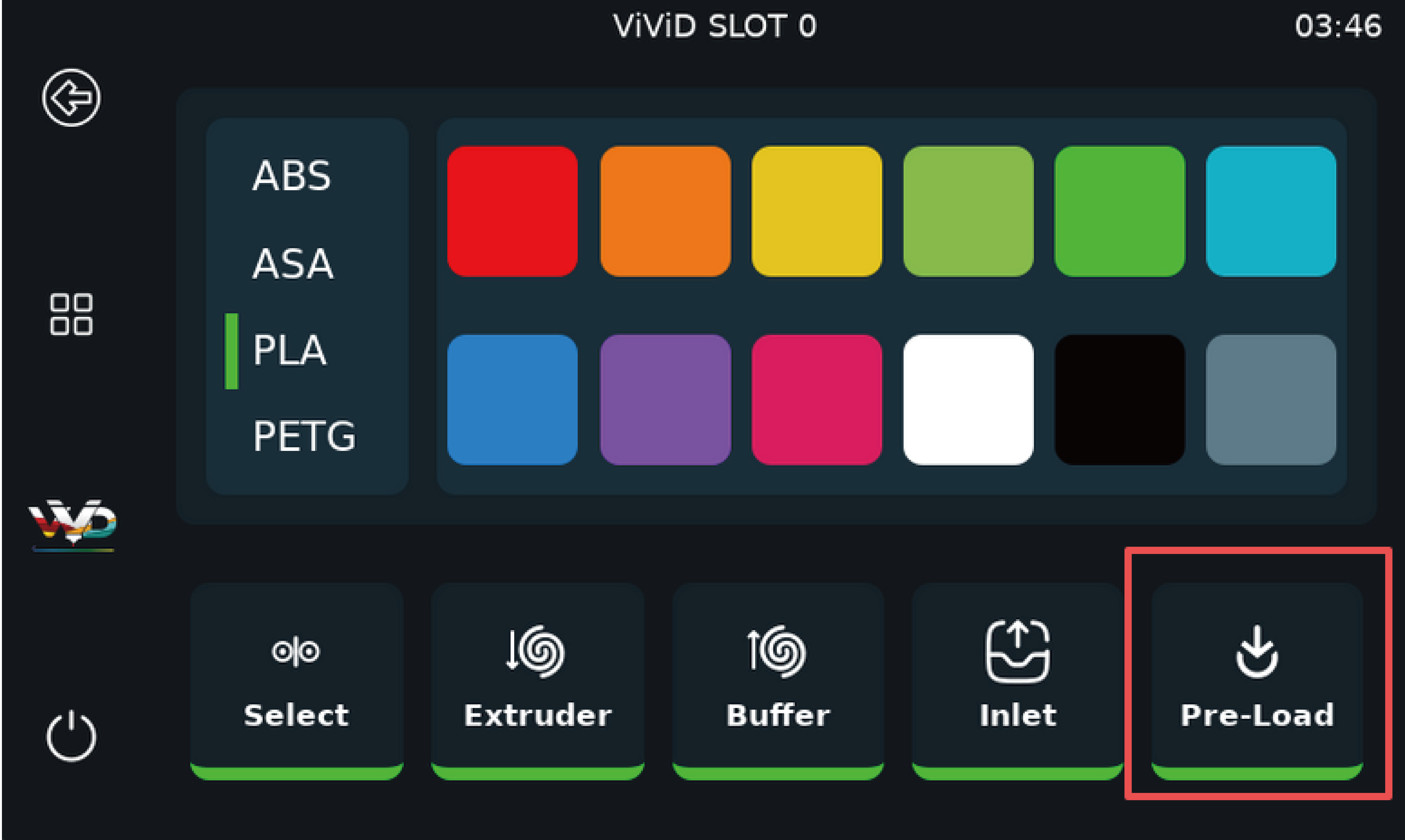
Tap the Pre-Load button.
-
Wait until the selector completes its homing and slot selection.
This can be confirmed when mechanical movement stops or a steady motor sound is heard.
-
Once the selector is in position, insert the filament straight and vertically into the corresponding inlet.
-
-
Using the Web Interface:
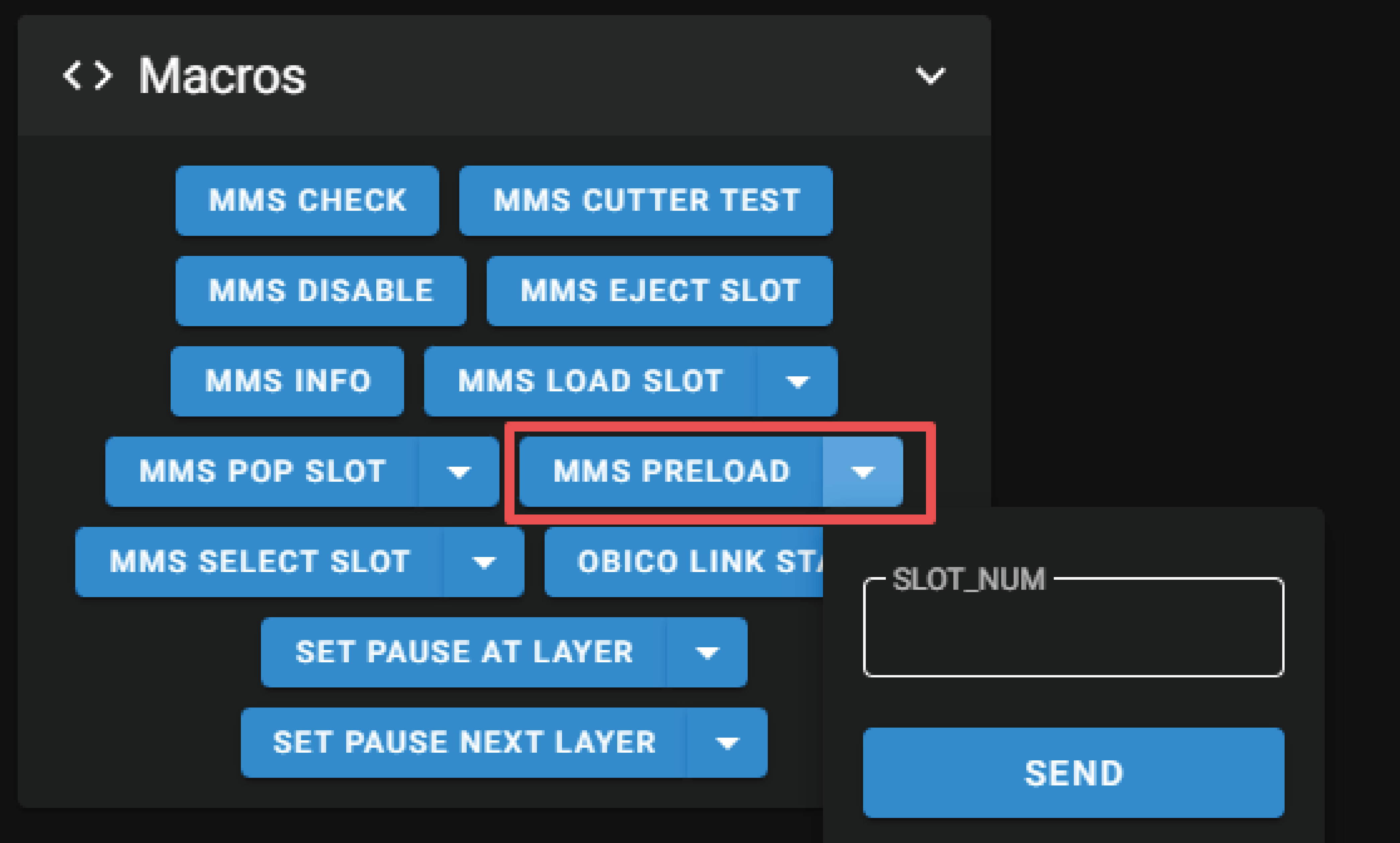
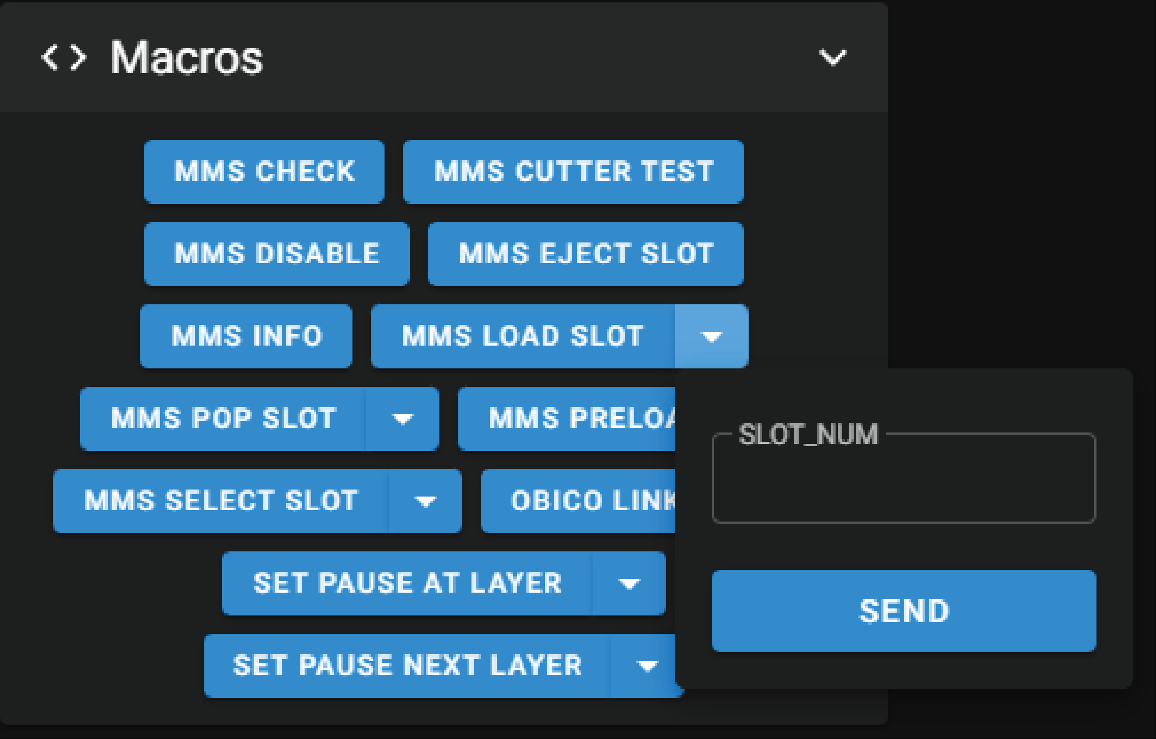
You can use the macro
MMS PRELOAD. Select the corresponding SLOT, click SEND, then manually insert the filament vertically into that SLOT. The filament will be drawn into the ViViD. Once the Gate sensor is triggered, the system will automatically preload the filament and retract it a short distance, placing it into a standby state.
Loading Filament to the Toolhead Extruder
-
Using KlipperScreen (ViViD-adapted version):
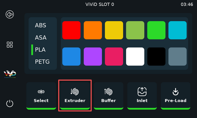
After the filament enters the buffer, select its corresponding slot. Then, enter the filament management interface for that slot and tap Extruder. The system will automatically feed the filament to the extruder. If heating is needed for loading, first enter the
MMS_BUFFER_ACTIVATEcommand in the console, then execute the extrusion command. -
On the Web Interface:
You can use the
MMS LOAD SLOTmacro. Enter the desired SLOT number and click SEND to feed filament from the selected slot into the extruder. Synchronized feeding is enabled by default.To extrude filament, manually heat the hotend and then issue the extrusion command.
Filament Unloading
Unloading Filament to the Buffer
-
Using KlipperScreen (ViViD-adapted version):

-
Enter the filament management page for the corresponding slot.
-
Tap BUFFER.
-
The filament will be retracted to a position outside the Buffer, with the Gate sensor no longer triggered.
If the filament is already inside the extruder: you need to execute
MMS_EJECTin the web console. -
-
Using the Web Interface:
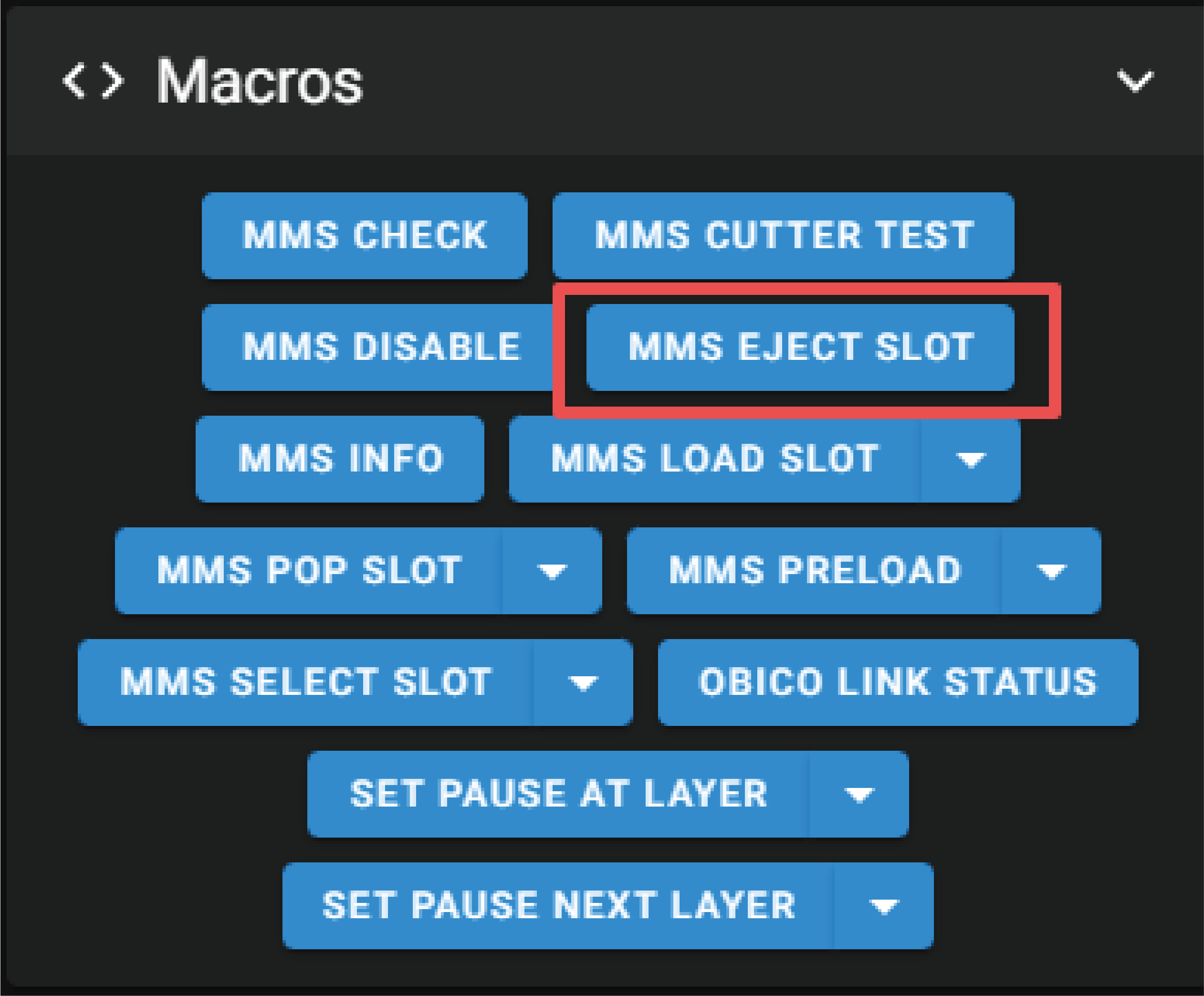
Use the macro
MMS EJECT SLOT. This will retract the filament from all slots to a position outside the Buffer where the Gate sensor is not triggered.
Unloading Filament Completely (No Filament State)
-
Using KlipperScreen (ViViD-adapted version):

avigate to the filament management page for the corresponding slot and tap Inlet. The filament will be pushed completely out of the feed path.
-
Using the Web Interface:
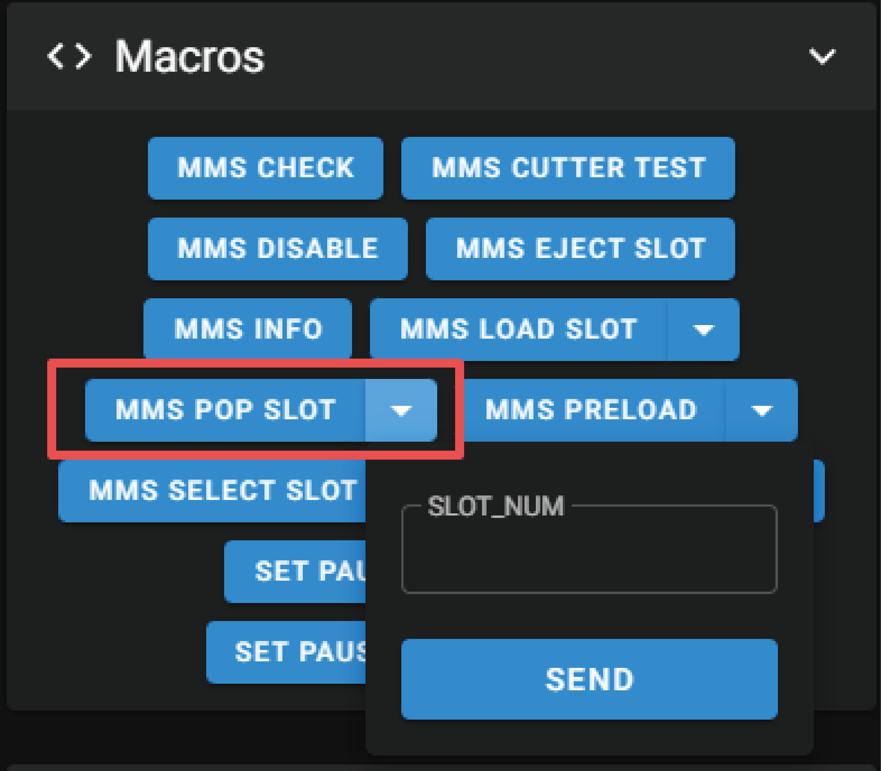
Use the macro
MMS POP SLOT, enter the corresponding slot, and after clicking “SEND”, the filament from the selected slot will be moved completely out of the feed path.Note: If the filament has already entered the extruder, you must first execute
MMS_EJECTbefore using Inlet orMMS POP SLOT.
Switching the Selected Slot
-
Using KlipperScreen (ViViD-adapted version):
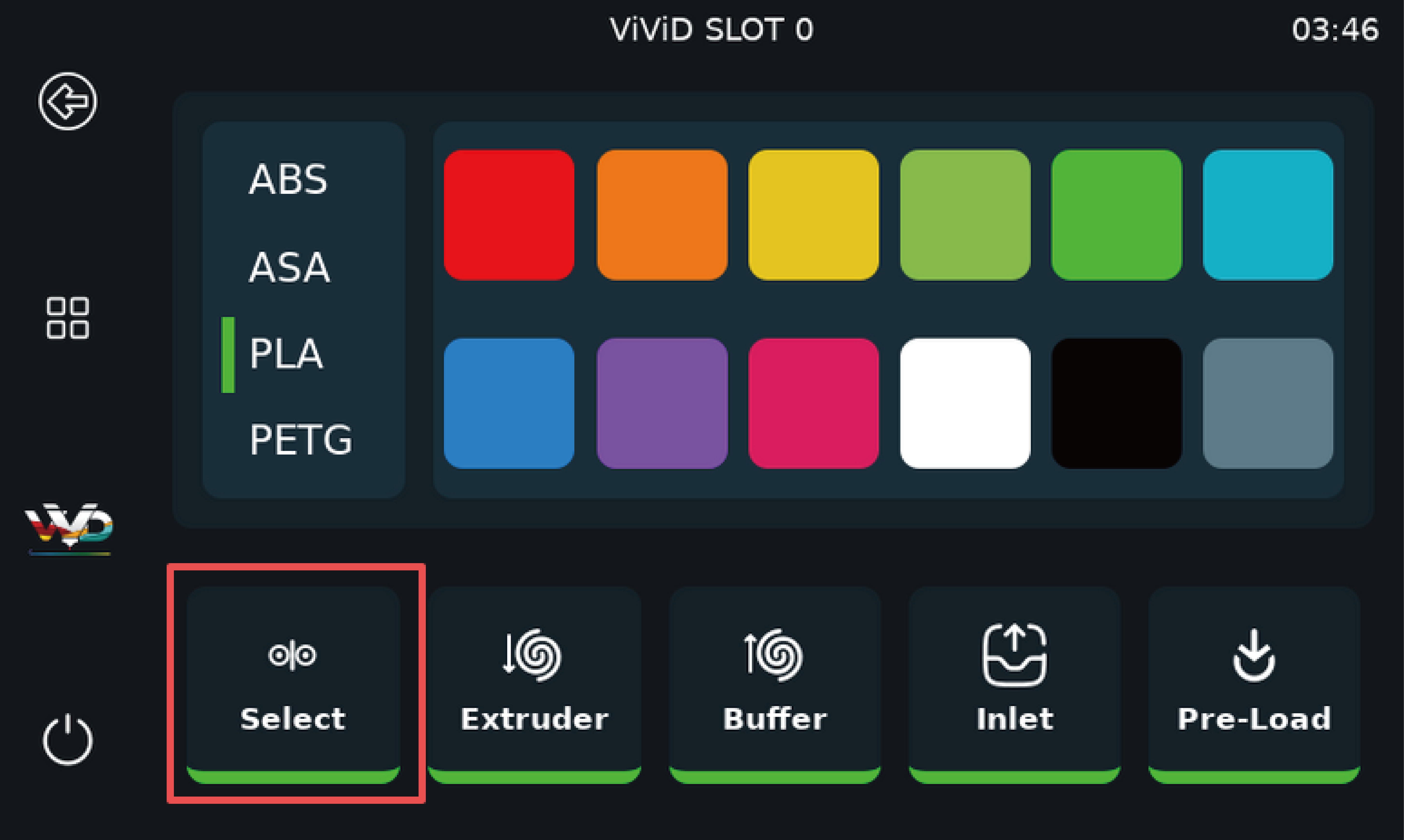
Enter the filament management page for the desired slot and tap Select. The selector will rotate and engage the corresponding slot.
-
Using the Web Interface:
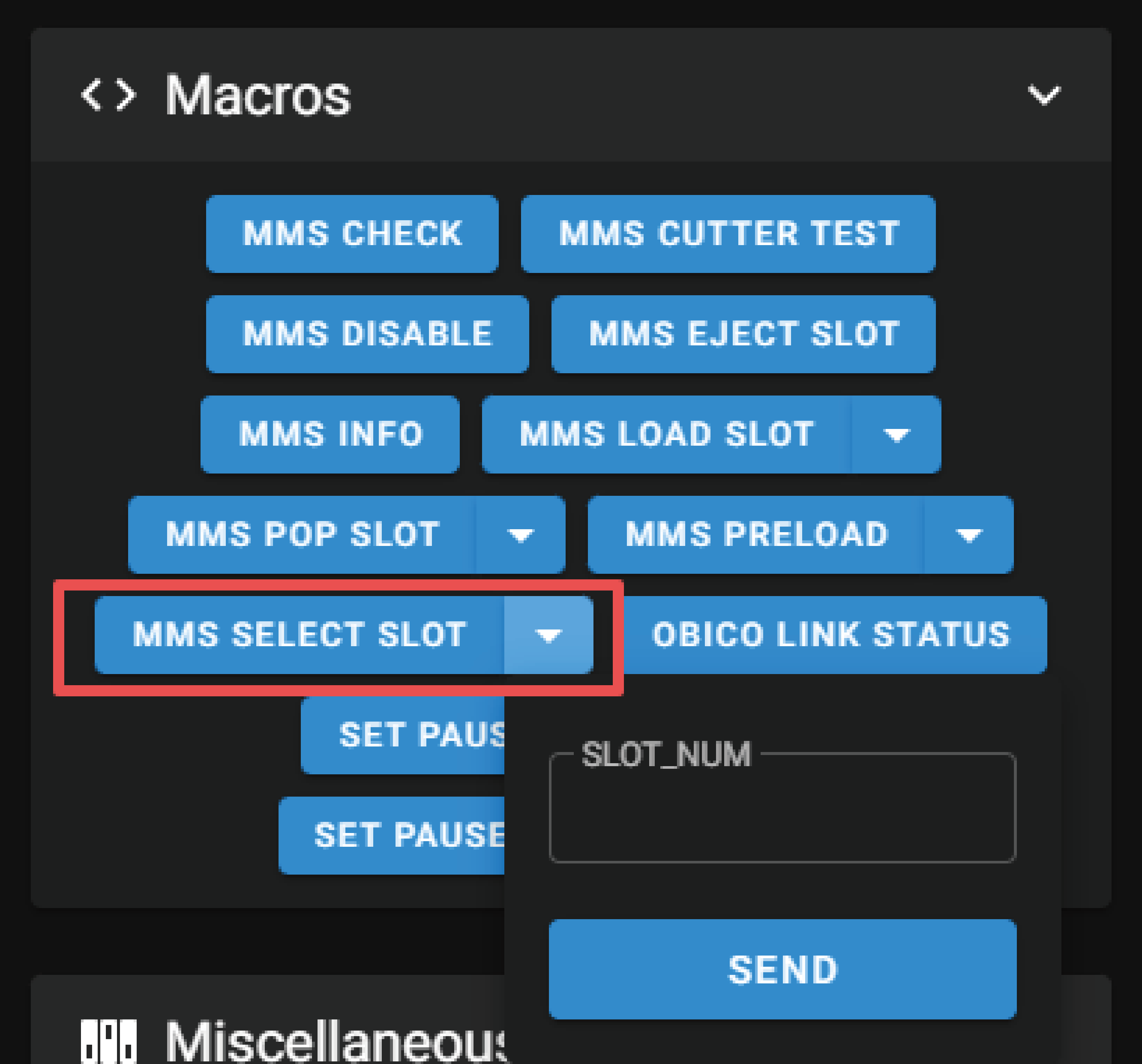
Use the macro
MMS SELECT SLOT, enter the corresponding slot, and after clicking “SEND”, the selector will select and engage the specified slot.
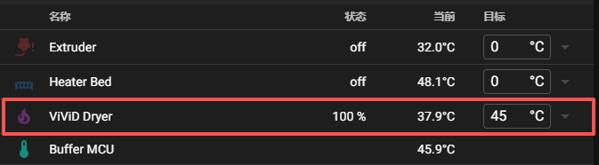
Chamber Heating
You can enable chamber heating by modifying the target value of ViViD Heater in Mainsail. If KlipperScreen (ViViD-adapted version) is installed, heating can also be enabled using the on-screen controls.
-
In Mainsail
-
In KlipperScreen
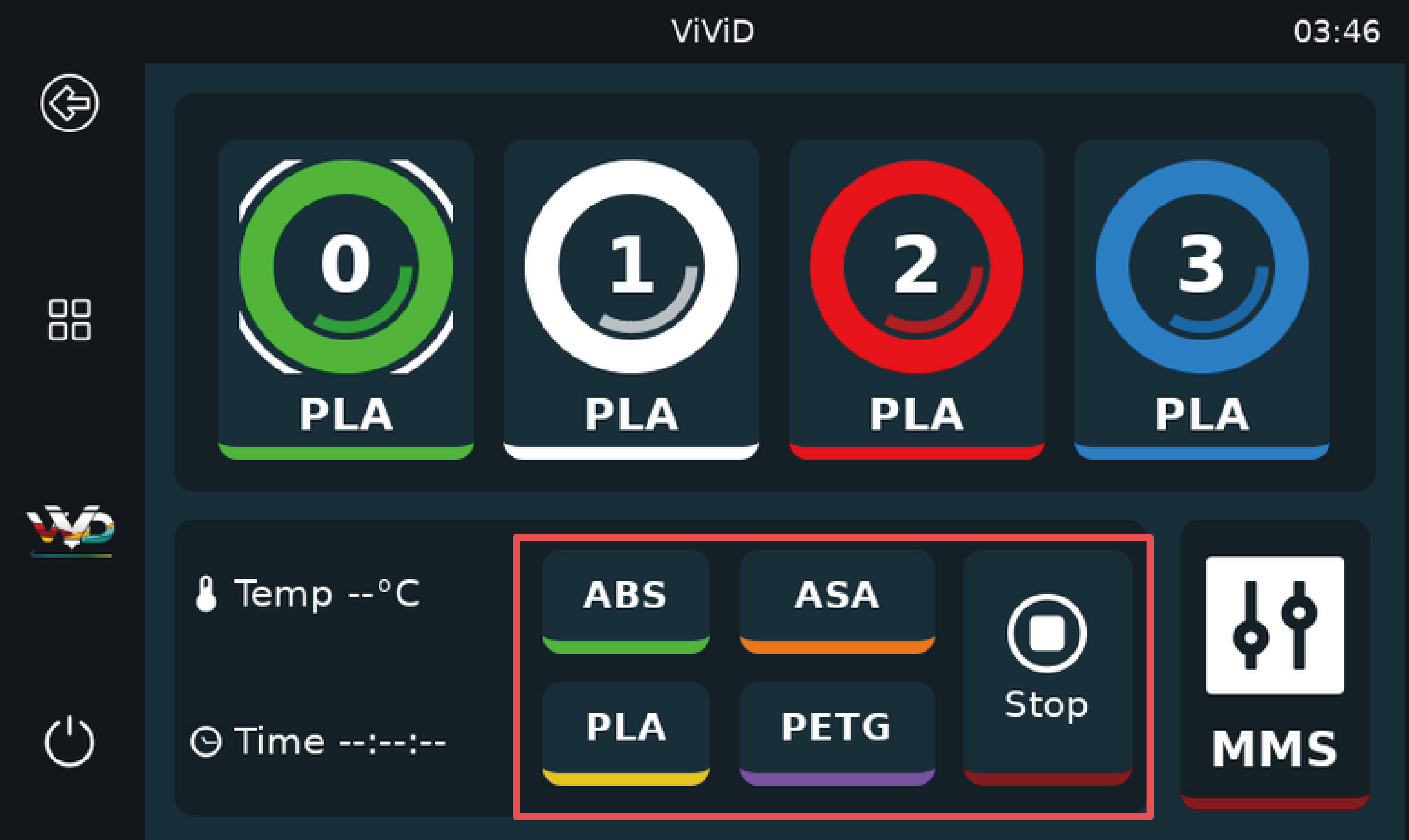
Recommended Drying Temperatures and Default KlipperScreen Drying Time
| Material | Temperature (°C) | Time |
|---|---|---|
| PLA | 45 | 4 h |
| PETG | 50 | 4 h |
| ABS | 55 | 4 h |
| ASA | 55 | 4 h |
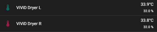
If high humidity is detected during heating, you can adjust the Humidity Exhaust Valve to open or close the vents, controlling airflow within the chamber. The temperature and humidity sensors are located on the left and right internal partitions of the chamber.
Open: When heating is enabled, opening the vents expels moisture, improving the effectiveness of filament drying.
Closed: When heating is disabled, closing the vents helps maintain internal humidity and prevents the filament from absorbing moisture.
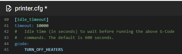
When chamber heating is performed in the idle state, the timeout value in idle_timeout must be adjusted accordingly.
To allow a complete heating cycle, it is recommended to set the value to 14400 seconds (4 hours).
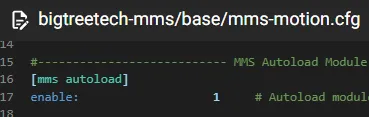
Automatic Filament Loading
After enabling this configuration, straighten the filament and place it into the corresponding SLOT. The filament selector motor will rotate quickly for alignment. Insert the filament only after the extruder starts moving. Be sure to wait until the motor has reached its position before inserting the filament, otherwise the filament may scrape out from the side.
Filament Runout Detection
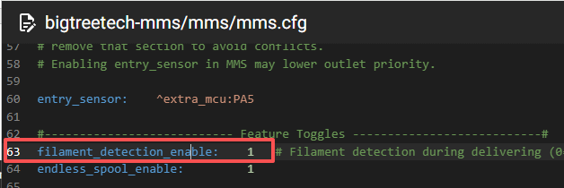
Filament runout detection is enabled by default. If the filament breaks or runs out during printing, the printer automatically pauses the print.
Before resuming, remove any remaining filament from the PTFE tube, then load a new filament spool. Once the filament path is clear and the new filament is properly loaded, printing can be resumed.
Filament Auto-Continue
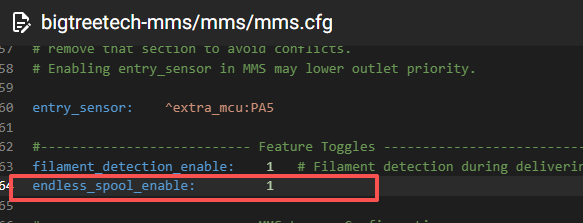
Because any residual filament remaining in the PTFE tube must be purged, the Purge function must be enabled for the auto-continue feature to operate correctly.
By default, when T0 runs out, the system automatically switches to T1, then T2, and continues in sequence.
Slicer Software Configuration
This section uses Orca Slicer as an example.
Please adjust the slicer settings according to the recommendations below.
Disable Filament Ramming in the Slicer
Whether you are using MMS or HappyHare, the filament change logic already includes filament ramming operations.
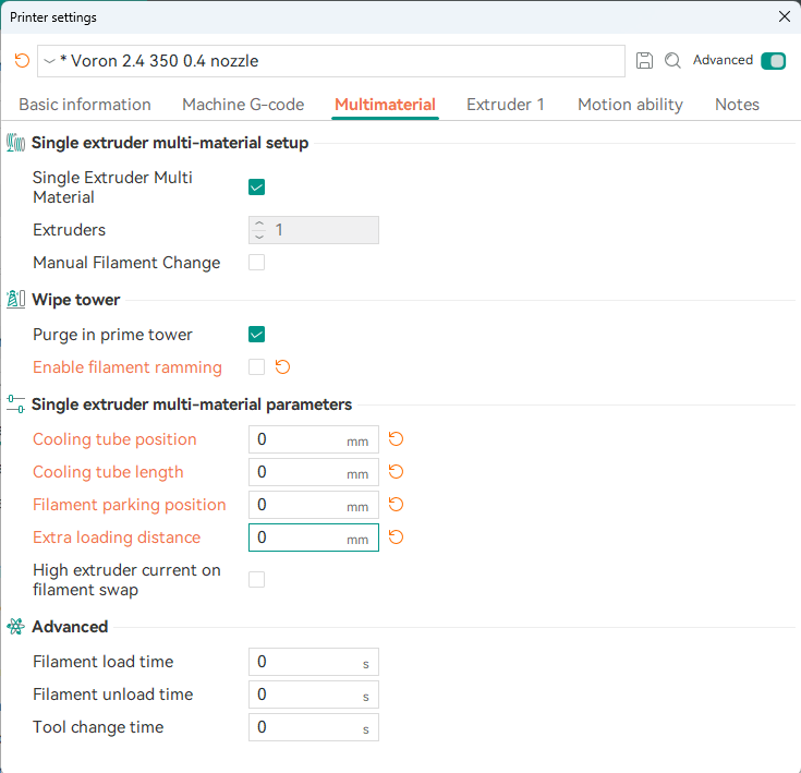
- Operation: Disable filament ramming generated by the slicer to prevent repeated ramming actions from causing re-melted filament buildup and potential hotend clogging.
- G-code Estimation: If you need more accurate G-code execution time estimation, you may manually enter the estimated time for each step in the slicer’s advanced options.
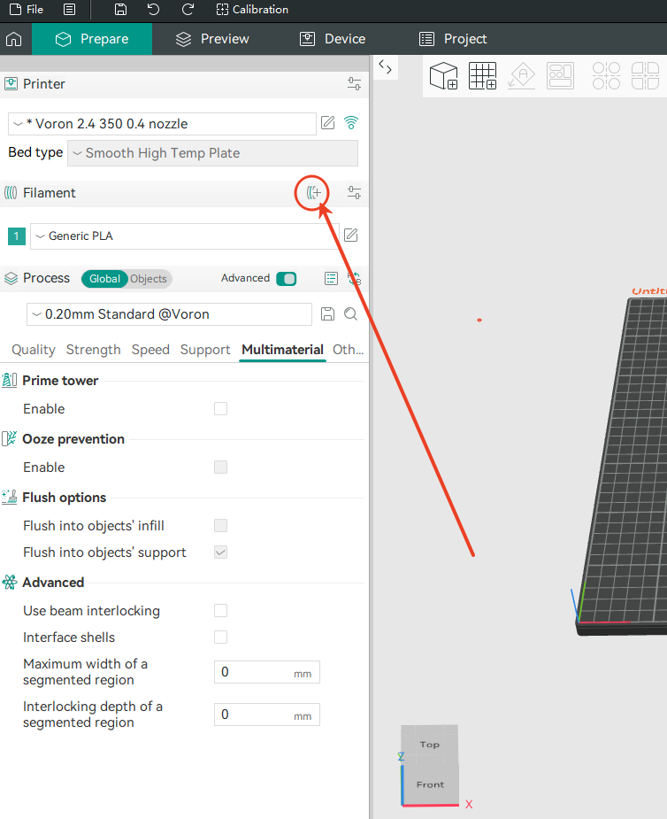
Enable Multi-Material Printing
Enable multi-material printing by adding multiple materials using the corresponding options in the slicer.
Important Notes:
- Multi-material printing must be enabled in your slicer when using ViViD; otherwise, the system will not function correctly.
- Avoid combining filaments with significantly different melting temperatures. The preheating required for a high-temperature material may cause a lower-temperature filament to soften or melt within the heatbreak, potentially leading to a clog.
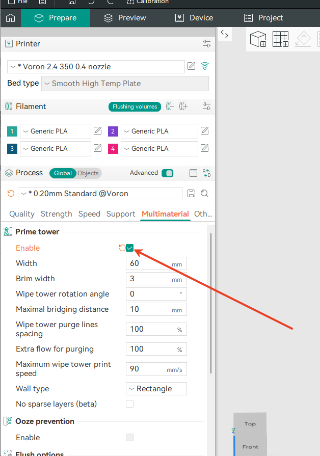
Enable Wipe Tower
You must enable the prime tower feature, as the it helps prevent color contamination during filament changes and reduces minor surface defects caused by oozing or residual filament.
Model Splitting and Material Assignment
Model Splitting: For most models designed for multi-color printing, you can use Orca Slicer's "Split" function to "Split to Parts".
This function can split components while preserving the model's original appearance design and relative positions.
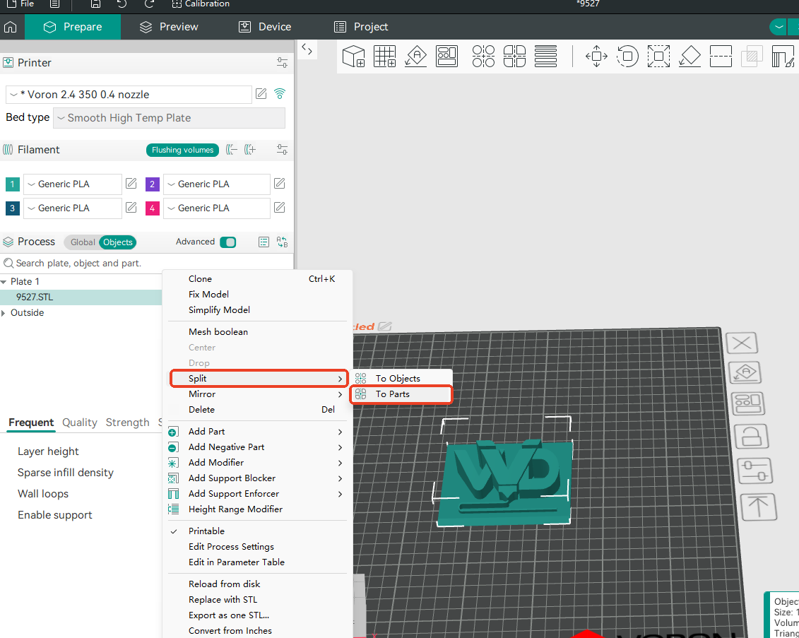
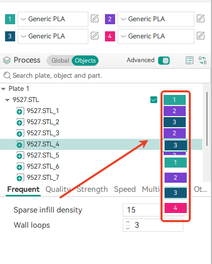
Assign Materials: You can assign different materials to each "part object" in the Process - Objects tab, or apply parameters using modifiers.
Purge Length Adjustment
After slicing, you may observe that different colors are assigned different purge lengths on the prime tower. This is intentional and ensures that the previously loaded filament is fully purged from the toolhead before the new color begins printing.
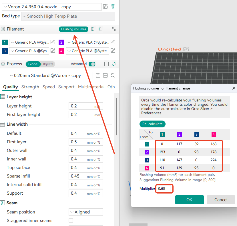
Adjustment: To reduce material waste, you may adjust the flushing volume values or apply a purge length multiplier.
Apply: After modifying any flushing parameters, you must re-slice the model for the changes to take effect in the newly generated G-code.
Additional Notes: If you observe overlapping paths in the sliced preview, select all model parts, combine them into a single group, and adjust the object order to determine which object takes priority in overlapping regions.
Tip: Detailed explanations of Orca Slicer’s advanced features are beyond the scope of this manual. Please refer to the official Orca Slicer documentation for further guidance.
Your multi-color slicing setup is complete!
Upload the generated G-code to your printer and perform a test print.
Happy printing!
Tuning Guide
Parameter Description
The install.sh script supports the following parameters:
| Parameter | Description |
|---|---|
| -h | Display help information (Help). |
| -i | Perform installation (Install). |
| -d | Perform uninstallation (Uninstall). |
| -g | Get version information (Get version). |
| -z | Skip the GitHub update check. By default, the script automatically checks for the latest version on GitHub. If you have modified the script locally, use this parameter to disable updates. |
Example: To skip the GitHub update check and uninstall MMS, run: ./install.sh -zd
Advanced MMS Usage
Custom Macro Interfaces
MMS provides custom macro hook interfaces for nearly every process, with the exception of the Load process.
Example: In the purge configuration file, you can find macro hook definitions such as: [gcode_macro MMS_PURGE_CUSTOM_START].
As a reference, BIGTREETECH provides a Blobifier macro example, which can be found in the official BIGTREETECH documentation.
Reducing a High Charge Failure Rate
If the extruder design makes it difficult to achieve a smooth transition between the end of the Load process and the start of the Charge process, you can try adding the following G-code to the charge_before macro:
# Example macro: Perform a short buffer-fill action before Charge
# Modify the macro name and content as needed
# [gcode_macro MMS_CHARGE_CUSTOM_BEFORE]
# gcode:
#     {% set slot_num_to = printer["mms swap"].slot_num_to if printer["mms swap"].slot_num_to else 0 %}
#     MMS_BUFFER_FILL SLOT={slot_num}
Note: If this macro does not significantly reduce Charge failures, structural adjustments may be required:
-
Check for excessive resistance at the Entry Sensor.
-
Check for steps, gaps, or sharp transitions between the PTFE tube and the extruder drive gears.
-
In some cases, mechanical modifications to the toolhead may be necessary to better support multi-material filament changes.
Troubleshooting Eject Failures
If filament fails to retract to a position in front of the Gate sensor during the Eject process, check the status information returned by MMS0 in the console.
-
If entry=1:
Verify that the cutter has successfully cut the filament and completed its retraction movement.
Check whether filament remains under the Entry Sensor and is holding it open.
-
Reliability Note: Users are responsible for ensuring the reliability and correct installation of all sensors mounted on the toolhead.
Other Information
Frequently Asked Questions and Troubleshooting
Q1: I cannot control ViViD to perform filament drying
A: First, verify that the SET_HEATER_TEMPERATURE macro has been overridden or modified.
A known cause of this issue is a bed fan control macro commonly used in the VORON community. This macro forcibly remaps heater inputs to the hotend, heated bed, and other heaters, while blocking temperature control commands for any heater classified as “other”.
To retain its original functionality while allowing other heaters (such as the ViViD heater) to operate correctly, modify the macro as follows:
[gcode_macro SET_HEATER_TEMPERATURE]
rename_existing: _SET_HEATER_TEMPERATURE
gcode:
  # Parameters
    {% set HEATER = params.HEATER|default("None") %}
    {% set TARGET = params.TARGET|default(0)|int %}

    # Vars
    {% set THRESHOLD = printer["gcode_macro _BEDFANVARS"].threshold|int %}

    {% if HEATER|lower == "extruder" %}
        M104 S{TARGET}
    {% elif HEATER|lower == "heater_bed" %}
        M99140 S{TARGET}
    {% else %}
        _SET_HEATER_TEMPERATURE HEATER={HEATER} TARGET={TARGET}
    {% endif %}

    # Set fans to low if heater_bed temp is requested above threshold
    # temp, and kick off monitoring loop.
    {% if HEATER|lower == "heater_bed" %}
        {% if TARGET >= THRESHOLD %}
        BEDFANSSLOW
        UPDATE_DELAYED_GCODE ID=bedfanloop DURATION=1
        {% else %}
        BEDFANSOFF
        UPDATE_DELAYED_GCODE ID=bedfanloop DURATION=0 # Cancel bed fan loop if it's running
        {% endif %}
    {% endif %}
Q2: Layer shifting occurs frequently when printing multi-color models
A: This issue commonly occurs after the toolhead cutter impacts mechanical structures, which may cause XY belt skipping or stepper motor missed steps.
Please perform the following checks:
-
Configuration checks: Verify that no configuration causes overtravel or collisions with structural components.
-
Homing method: Sensorless homing is not recommended for multi-color printers that use a toolhead-mounted cutter.。
-
Motor temperature: If the above issues are not present, check the stepper motor temperature:
- If the temperature is not excessively high, you may slightly increase motor current.
- If the temperature is too high, consider adding additional motor cooling or lowering the chamber temperature during printing.
Q3: Filament slips out from the side of the feed path
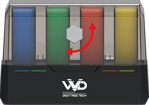
A: Due to the operating principle of ViViD, the selector motor applies pressure to the filament after rotating. If the filament is inserted at an angle, this pressure may cause the filament to slip out sideways.
Solutions:
- Option 1: Switch the selector to another slot, straighten the filament, and insert it vertically.
- Option 2: Straighten the filament first, then use the “Pre-Load” function. For details, refer to the filament loading instructions in Section 4 of this manual.
Firmware Compilation Options
Manual firmware compilation is not recommended, as it may disable certain preset functions (for example, the status indicator LED behavior when the device is not connected to the host).
If a firmware update is required, both the ViViD main unit and the Buffer module come pre-installed with Katapult (formerly known as CanBoot). You can use Katapult’s flashtool.py to flash firmware provided in the official GitHub repository.
Firmware Flashing Example (The following example is for demonstration only. Replace the device ID and firmware path with your actual values):
-
Retrieve device ID:
-
Execute the flashing command:
python3 ~/katapult/scripts/flashtool.py -d /dev/serial/by-id/usb-Klipper_stm32g0b1xx_vivid_320038000A50425539393020-if00 -f ~/katapult/g0b1_usb_klipper-12-04.bin-dspecifies the device ID obtained above-fspecifies the firmware file path
If manual compilation is absolutely required, use the following settings:
| Module | MCU Model | Notes |
|---|---|---|
| ViViD Main Unit | STM32G0B1 |  |
| Buffer Module | STM32F042 |  |
Important – Buffer Firmware Compilation: The STM32F042 has limited flash memory and cannot accommodate the full Klipper firmware. When compiling Buffer firmware, strictly follow the compilation instructions and disable certain features in the configuration menu to reduce firmware size.
Optional Configurations
Hardware: Blobifier
The Blobifier module generates and stores purge waste in a compact and high-density form.
Advantage: This method reduces build plate contamination from accumulated purge waste and makes purge waste removal more efficient and convenient.
Software: Spoolman (Spool Management)
At the time of writing this manual, MMS does not yet support Spoolman.
-
For HappyHare users: Spoolman can be used to manage filament spools conveniently.
-
Filament labels: While structural limitations may prevent ViViD from reliably reading Bambu Lab RFID tags, custom label solutions are available. Labels can be manually transferred when changing spools.
-
Future integration: Orca Slicer is expected to add Spoolman support in future releases.
-
Final goal: The intended user experience is to synchronize filament information across the MMU, slicer, and database - similar to the ecosystem provided by the Bambu Lab AMS.
Thank you for following this guide to set up your BIGTREETECH ViViD Multi Color Management System. By carefully completing the hardware installation, firmware configuration, and slicer integration, you have equipped your printer with advanced multi material capabilities.
For ongoing support, firmware updates, and community resources, please visit the official BIGTREETECH documentation and GitHub repository.
For immediate troubleshooting, please refer to the relevant sections in this manual. If your specific issue is not covered, we recommend consulting the wider user community for additional guidance.
We wish you successful and vibrant multi color printing.